
CSA & cleanroom fit-out
Civil, structural and architectural interfaces; cleanroom partitions, ceilings, finishes and coordinated people and material flows.
Fuji CAC brings cleanrooms, HVAC, electrical systems and process utilities into one coordinated facility package for semiconductor, electronics and advanced manufacturing projects in Vietnam.
New facilities, rented-factory conversions, expansions and cleanroom renovations each need a defined design basis. Delivery may be an integrated Design & Build / general contractor package or a specialist scope, with responsibilities agreed for each project.
Civil, structural and architectural interfaces; cleanroom partitions, ceilings, finishes and coordinated people and material flows.
Air handling, filtration, pressure relationships and utility distribution; process gases, DI water and equipment connections within the agreed scope.
Power distribution, ELV, BMS/FMCS interfaces and monitoring, coordinated with installation, testing and commissioning.
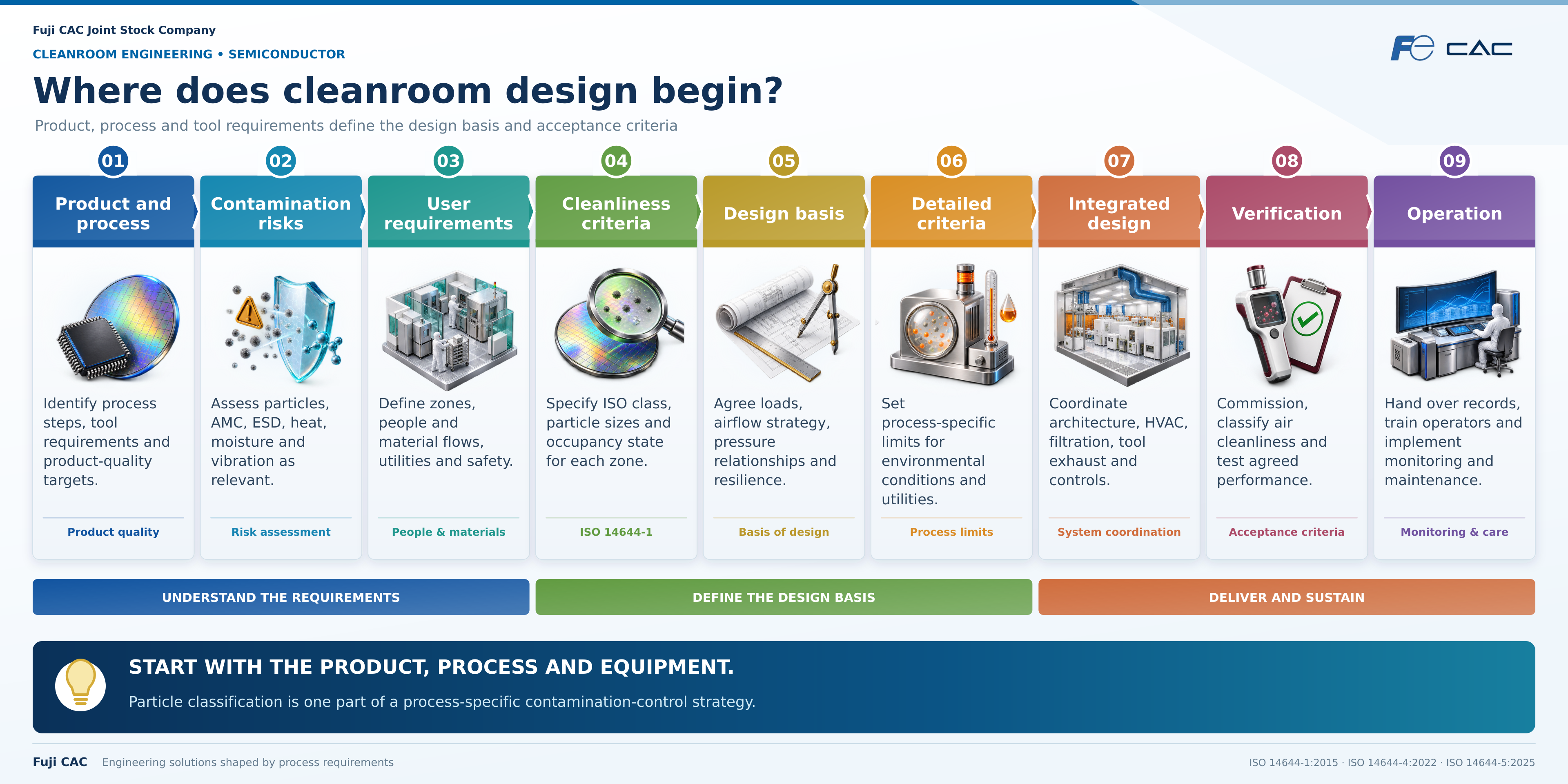
Identify process steps, tool requirements and product-quality targets.
Assess particles, AMC, ESD, heat, moisture and vibration as relevant.
Define zones, people and material flows, utilities and safety.
Specify ISO class, particle sizes and occupancy state for each zone.
Agree loads, airflow strategy, pressure relationships and resilience.
Set process-specific limits for environmental conditions and utilities.
Coordinate architecture, HVAC, filtration, tool exhaust and controls.
Commission, classify air cleanliness and test agreed performance.
Handover records, train operators and implement monitoring and maintenance.
A common configuration for semiconductor and electronics cleanrooms combines a make-up air unit (MAU), fan filter units (FFUs) and dry cooling coils (DCCs). Air returns through a perforated raised floor and the underfloor plenum, completing a controlled recirculation loop.
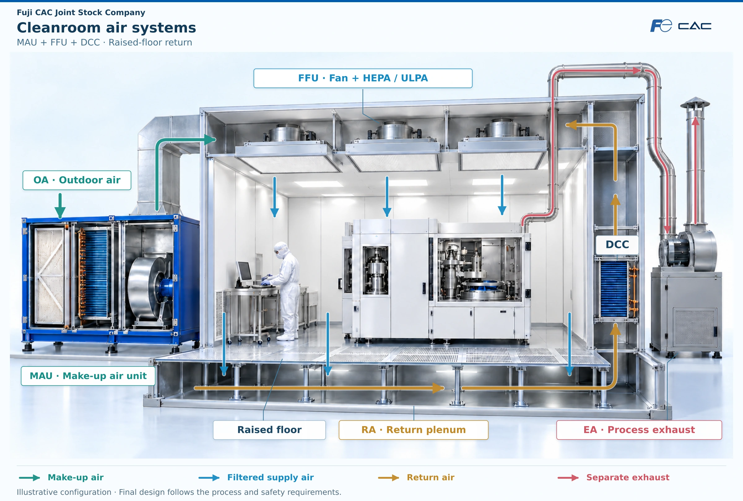
MAU make-up air joins the ceiling plenum. FFUs circulate air through the room, raised-floor return and DCC; process exhaust leaves separately.Outdoor air → MAU filtration and conditioning → ceiling supply plenum. Make-up air replaces exhaust and leakage losses.Ceiling plenum → FFU / HEPA or ULPA → cleanroom → perforated raised floor → return plenum → DCC → ceiling plenum.Process equipment → dedicated exhaust duct → exhaust fan → discharge / treatment as required. No connection to the room-air recirculation loop.
Illustrative airflow · Animation speeds do not represent design velocities.
The MAU filters and conditions outdoor air, including cooling and dehumidification. Make-up air is balanced against exhaust and room leakage; reheat or humidification is added when required.
Ceiling-mounted fan filter units draw air from the supply plenum and deliver it to the room through HEPA or ULPA filters selected for the process.
Air passes down through perforated floor panels into the underfloor return plenum, then rises through the side return shafts.
Dry cooling coils cool the return air before it re-enters the ceiling plenum. Coil surfaces stay above the local air dew point to avoid condensation; the FFUs circulate the air again.
Wafer fabrication, assembly, packaging and test do not share one universal cleanroom class. Assess room-level and tool-level protection separately. A mini-environment can provide local protection where justified by the process.
Specify temperature, relative humidity, pressure relationships, vibration and process lighting from tool and product requirements. Establish an ESD control programme where applicable; humidity control alone does not demonstrate ESD protection. ISO particle class does not prescribe a universal ACH, pressure difference, room velocity or filter coverage.
Assess AMC separately where chemicals threaten the product or process. HEPA/ULPA particulate filters do not, by themselves, demonstrate control of gas-phase molecular contaminants. Hazardous tool exhaust requires dedicated containment and compatible exhaust/treatment arrangements. Room pressure must satisfy both contamination control and safety; positive pressure is not appropriate for every space.
Agree commissioning and acceptance tests before design freeze. Depending on scope, these can include particle classification, installed-filter leakage, airflow, pressure, temperature/humidity, airflow visualisation, recovery and safety interlocks. Monitoring follows an agreed risk-based plan. IQ/OQ/PQ may be used under the client’s qualification framework; it is not a universal semiconductor handover requirement.
See how people, materials and controlled air move through a cleanroom—from the room layout to the temperature concept.
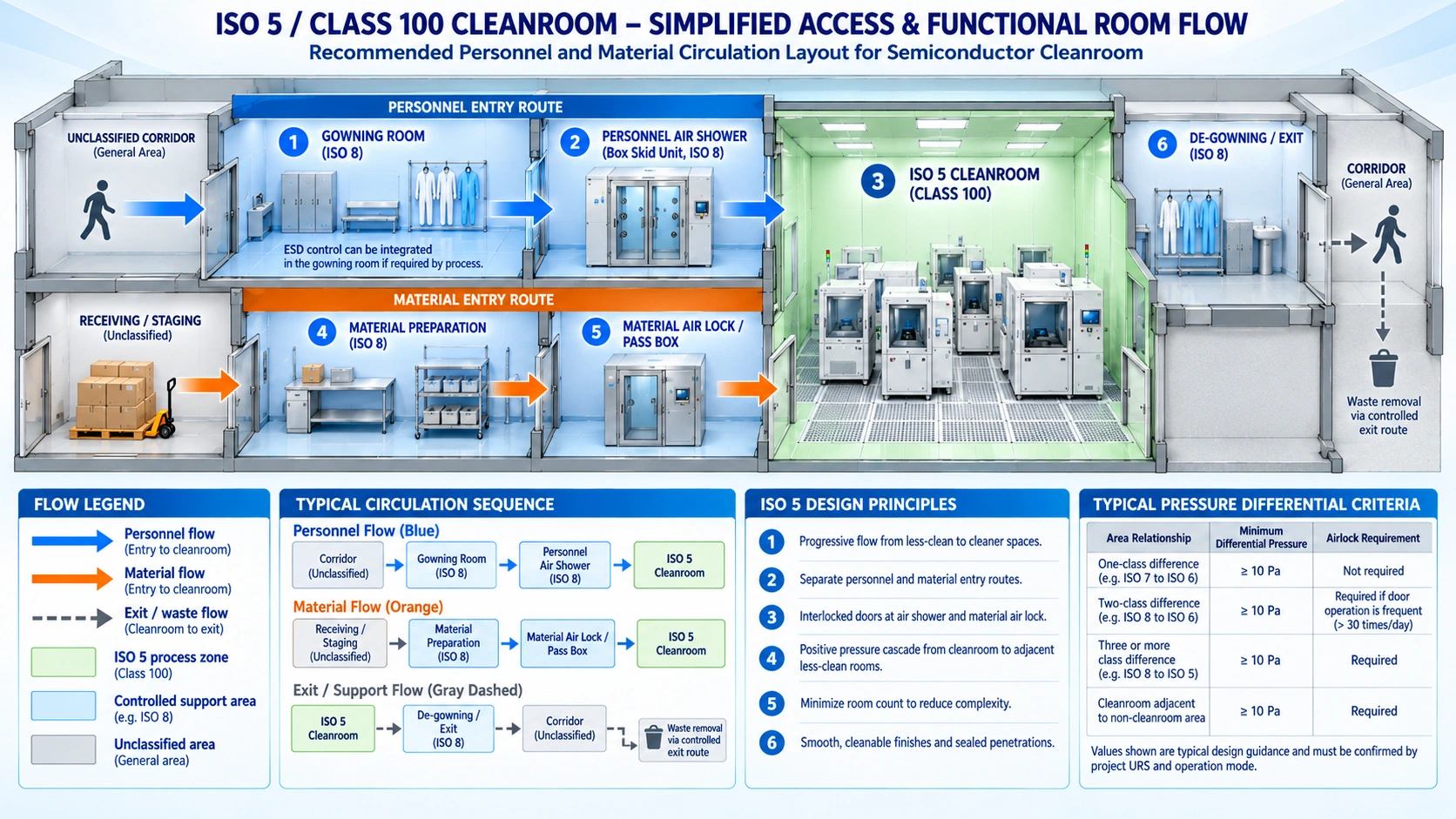
Gowning → controlled personnel entry → process room
Preparation → material airlock or pass-through → process room
De-gowning and controlled removal routes, coordinated with operations
Illustrative zoning: room grades, air showers, airlocks and pressure relationships are selected for the process. “Class 100” is an approximate legacy comparison to ISO Class 5 at ≥0.5 µm.
A 22-second concept animation follows MAU supply, FFU downflow, equipment heat, raised-floor return and DCC cooling.
The displayed temperatures and room dimensions are example assumptions. This concept animation is not a validated CFD study or evidence of ISO Class 5 performance.
| ISO 14644-1 | ISO limit particles/m³ at ≥0.5 µm | Legacy FS 209E English class |
|---|---|---|
| ISO 3 | 35 | ≈ Class 1 |
| ISO 4 | 352 | ≈ Class 10 |
| ISO 5 | 3 520 | ≈ Class 100 |
| ISO 6 | 35 200 | ≈ Class 1 000 |
| ISO 7 | 352 000 | ≈ Class 10 000 |
| ISO 8 | 3 520 000 | ≈ Class 100 000 |
FS 209E was withdrawn on 29 November 2001. Its English class numbers use a particles/ft³ basis. This is an approximate crosswalk at ≥0.5 µm, not an interchangeable full classification or test method. Specify the zone, ISO class, particle size(s), occupancy state and agreed verification criteria.
Design & Build of electrical infrastructure, utility distribution and CSA works, including cleanroom renovation and facility upgrades.
Read the scope of workDesign & Build of CSA, cleanrooms, electrical systems, HVAC, process gases, DI water and fire protection for a semiconductor facility.
Read the scope of workGeneral contracting for coordinated building fit-out, MEPF and process utilities, including installation, testing, commissioning and handover.
Read the scope of workNo. At the cumulative particle-size threshold ≥0.5 µm, ISO Class 5 is approximately comparable to legacy FS 209E Class 100, and ISO Class 6 to Class 1,000. The comparison does not replace full classification or the agreed testing method.
No. Define the product, process steps, equipment and contamination risks first. The ISO particle class, occupancy state, environmental controls and utility requirements are then specified for each zone.
Fuji CAC’s documented experience includes conversion of existing warehouses into manufacturing facilities. Feasibility depends on the building condition, available utilities, layout, process requirements and agreed scope.
Send the project location, available drawings, production process, cleanroom area, target class and occupancy state if known, equipment utility requirements, expected delivery scope and target schedule.
Share your location, floor plan, production requirements and target schedule. Our team can discuss the facility scope, engineering interfaces and next information needed.
General technical guidance. The project design basis, applicable standards and acceptance criteria are agreed for each facility.